Motherboards are the foundation of computers. Motherboards, are used for smartphones to servers and everything in between… they all have a motherboard. It provides connectivity between all parts required to make your computer run. Modern motherboards are comprised of several components. This article will talk about the common pieces, what they do and why they’re needed.
Parts of A Motherboard

Example of a Desktop Motherboard. Brand: ASUS
1. PS/2
This is a legacy port used to connect peripheral devices such as keyboards and mice to your computer. Originally, this was the main way to connect a keyboard or mouse. If you stumble upon a device with the unique PS/2 connection, This is where you’d connect them. In example ASUS desktop mobo depicted above, there’s only one port. Either a PS/2 mouse or a keyboard could be used with it. The modern approach to connect keyboards and mice is via a USB port.

2.USB Ports (2.0)
USB Ports are the modern way to connect a plethora of devices. You’ll connect such things as keyboards, mice, flash drives, external drives, cell phones, meters, adapters and more. It’s a port with bi-directional data transfer. This means that a functioning computer can both send and receive data from a USB connected device, and vice versa. The have made newer versions of the USB port. The 2.0 version is somewhat dated, but very common. It’s max transfer rate is 480Mb/s. To put it in reference, a movie file of 2GB roughly over 30 minutes to copy from one device to another. That’s assuming the file could be copied over at the max transfer rate of 480Mb/s. This port is also compatible with older devices that use USB version 1.1.

3. VGA
This is a legacy video display port to connect a monitor or TV to your computer. VGA stands for Video Graphics Array. A VGA connection is not recommended for current high resolution monitors. It’s max resolution is 2048×1536. It’s initial max was 640×480 at refresh rate of 60Hz. Though it is capable of resolutions of 2048×1536, it’s not recommended to utilize this port, which may not properly render graphic signals properly from the system to the monitor(s). There is also no audio signal provided from this port either. This legacy port is eventually proceeded by other graphic ports that allow the motherboard or GPU (if utilized) to indeed transfer both graphics and audio simultaneously.

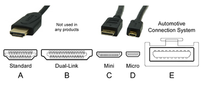
4. HDMI
HDMI is the modern approach to display audio and video created from your system to an HDMI compatible Monitor or TV. It is the current common successor of the VGA. A standard in all current TVs and most, if not all computer monitors. There are multiple versions of HDMI. Each iteration improves on the color, audio and pixels transferred to the visual device. Later versions even support transferring ethernet and 3D graphics data. HDMI allows for support of display graphics on 4K and 8K monitors at high refresh rates of 240Hz and more.
All motherboards do not possess video display ports (VGA, HDMI or otherwise). Those that do have visual display ports support Onboard Graphics. This is a feature in which a compatible CPU connected to the mobo will be able to process graphics without an dedicated GPU. The Onboard graphics do normally use the standard HDMI port. Your HDMI cable type may depend on the output device (monitor or TV). All output devices do not use standard HDMI or even have HDMI, which may require the need of an adapter.
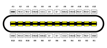
5.USB Ports (3.0) and 7. USB Ports (3.0)
The USB 3.0 ports are readily identified by the blue port connector. Earlier USB ports will have a white port connection. If they are a USB Type-C or Type-B, they it will be identified by the shape. Similar to the USB 2.0, but with even faster transfer rates. These transfer rates are blazing fast of up to 5GB/s and 10GB/s. That’s roughly 100 or 200 times faster than USB 2.0 max speeds. USB 3.1 is the latest standard to be released and commonly used with all types of devices. Highly recommended for quick data transfers. More mid to higher-end motherboards are also supporting fast charging mobile devices if connected to specific USB 3.0 ports.


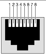
6.Ethernet Port
This is where you will connect your RJ-45 cable, commonly known as the Ethernet cord. You use this cord to connect your system to the internet via a router/modem. Depending on equipment, motherboard limits and ISP, you can transfer speeds of up to 10GB/s. To achieve such limits, you’d have to use CATe7 standard Ethernet cable, the on-board network capabilities of such rate and an ISP allowing such rates through the recommended router/modem.
If you do any kind of gaming or want a reliable steady connection to the internet, you’ll want to use this versus a WiFi Connection. Though WiFi may be convenient less wires to deal with, you’re guaranteed a faster connection always through the Ethernet cable.
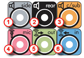
8. Audio Jacks
Audio jacks are a set of ports/jacks used to connect various audio related cords to either transmit or receive sound. The default use and functionality of each jack is color coordinated. The top three (1-3) are used for surround sound setups. They’re all output jacks. The bottom three (4-6) are the minimum you may see on a motherboard. They’re the normal audio jacks you’ll use for basic setups. Each jack (by default) is connect to the following:
- Side – Side/Middle Surround Sound Speakers for 7.1 setup
- Connect your side Surround Sound Speaker plug into this jack and the split plugs into the rear speakers.
- Rear – Rear/Back Surround Sound Speakers for 7.1 setup
- Connect your rear Surround Sound Speaker plug into this jack and the split plugs into the rear speakers.
- C/Sub – Subwoofer and center output
- Connect the cable from your subwoofer into this jack and the other end(s) into the subwoofer.
- Mic – Microphone Input
- Connect your Microphone cord to the input.
- Out – Headphone/Headset Output
- Connect your headphone or headset into this jack
- In – Stereo Line-in.
- Used to plug in external audio devices such as a sound board mixer or musical instrument.
Once you’ve started up and have access to your system’s control panel, you can actually modified the purpose of the jacks as desired. Though for simplicity, it’s better to leave this alone to not cause confusion. Though if needed, the option is available to you.
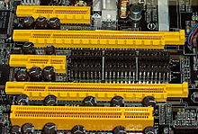
9. PCIe 3.0 x16
PCIe stand for Peripheral Component Interconnect Express is a high speed expansion bus standard. It’s used to attach external components to your motherboard to use it with high speed. The common use for PCIe slots are dedicated GPUs, sound cards, network cards, high-speed data storage devices, and device controllers (e.g, RAID controller). There are four speed types: x16, x8, x4, and the standard x1. The latest and common is the x16. the PCIe x16 provides the fast transfer rates to the motherboard. Devices connected via PCIe run the fastest compared to SATA or M2 sockets/ports.
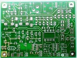
10. Special PCB
A PCB or a Printed Circuit Board is the base of a motherboard. It is the surface of all motherboard with the various metallic lines laid on the board. These elegant lines serve both functional and visual purposes. They are in a sense documentation of the expected location of components on the board. They’re also comprised of semiconductors, connectors, resistors, diodes, capacitors and radio devices so all components of the built system to talk communicate with each other.
Some motherboard may have more unique features than others with their designs. Some may enable better wireless communication, noise dampening and clearer signal transmission.
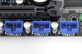
11. Front USB 2.0 Header
It is internal USB connection port reserved for devices requiring this port. As expected from the name, these headers are normally used to connect a component located on the front of your computer case. More modern cases may need this and/or USB 3.0 or USB 3.1. These headers could also be useful for connecting other internal parts such as, fan controllers, RGB light controllers, internal diagnostic displays and AIO liquid cooling units. If the connected component is, lets says, a USB hub, it will only transfer data at the rate of USB 2.0 if connected to a USB 2.0 header.
An easy tell that you’re looking at a USB 2.0 header is that it is a 9-pin port. It’s usual positioned at the bottom of the motherboard. Also, the bottom right corner of the header does not have a port. This space acts as a ground. Also helps make it easier to know your connecting the cable in the correct position.
12. SATA Ports
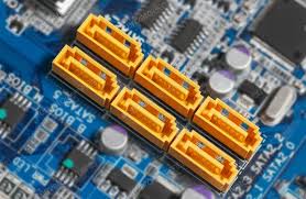
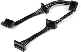
SATA stands for Serial AT Attachment. It’s commonly used for connecting storage drives (hard drives and solid state drives), and similar components. Though not as commonly included as it once was, DVD/CD/Blu-Ray drives would be connect via SATA ports. These drives would need both a data cable, connecting to the motherboard and a SATA power cable, which would stem from the PSU.
Some motherboards have the capability of utilizing what’s called RAID technology. RAID stands for Redundant Array of Inexpensive Disks. They can control a series of SATA connected drives (sometimes even PCIe ones as well) so they virtually behave as one single drive. This technique of RAIDs is useful for data resiliency and scaling.
There are three versions of SATA interfaces currently available:
- SATA I (previously called SATA 1.5Gb/s) – This first-gen of SATA being able to transfer up to 150MB/s. The running speed was 1.5Gb/s.
- SATA II (previously called SATA 3Gb/s) – The second iteration of the SATA ran at 3Gb/s and had a bandwidth throughput of 300MB/s.
- SATA III (previously called SATA 6Gb/s) – The third and latest runs at 6Gb/s and can transfer data up to 600MB/s.
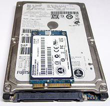

13. M2 Port
The M2 or M.2 port accommodates a form factor for modern storage devices. It is the next advancement in SSD technology. It supports NVM Express (NVMe) as the logical device interface for M.2 PCI Express SSD. The M.2 SSDs come in several varieties. It’s important note that besides storage capacity, they also can differ in physical dimensions and key connection. These keys leverages a different interface. For example: an M.2 with an A key, leverages USB 1.0 and standard PCIe, where as a M key will leverage PCIe x4 interface. These are important because all motherboards will not take all M.2 SSDs. You will need to refer to your manual for the accepted M.2s for your motherboard. This can cause damage and/or failure to one or more of your components if installed improperly.
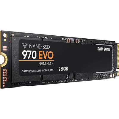
If you want to make sure your storage device isn’t the reason your system is bottlenecking and slow, utilize a M.2 drive.
14. Chipset
Chipsets of a motherboard is what really handles the communication of all connected devices on the CPU. It dictates limits of RAM and storage sizes, what CPUs can be used, as well as how everything does talk with each other. It provides the instructions so that everything can work in unison. Though the chipset provides the instructions for how everything can work, there still can be limitations on what the actual motherboard can handle.
The chipset’s important when it comes to choosing the CPU to build with. With each CPU that comes out, it can be a part of a different generation. Each generation may require it’s own new chipset to work. There are some chipsets and CPUs that are backwards compatible. It’s always important to check with the user manuals of both your CPU and motherboards for compatibility.
15. Front USB 3.2 Header
This is the latest generation of USB interface often used in mid to high-end motherboards. Just like it’s predecessor, it’s commonly used to connect to the front of the computer case. This connection allows for data transfers 20Gbps, one direction. If data is bi-directional, it then becomes halved to 10Gbps. Still, very impressive.
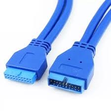
It’s fail-proof design for connection makes it a favorite of mine as well. The pin count header shape is distinct from the USB 2.0 header. It has all pins equally filled and used. There’s also a ridge in the middle that lines up perfectly with cable, minimizing potential of improper plug-in. On a motherboard, there can be one or more. Depending on the tier of modern motherboard and you could up to four USB 3.2 headers to connect to. This is not a set-in-stone standard or limit, but an observation of today’s motherboards.
16. CPU Socket
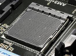
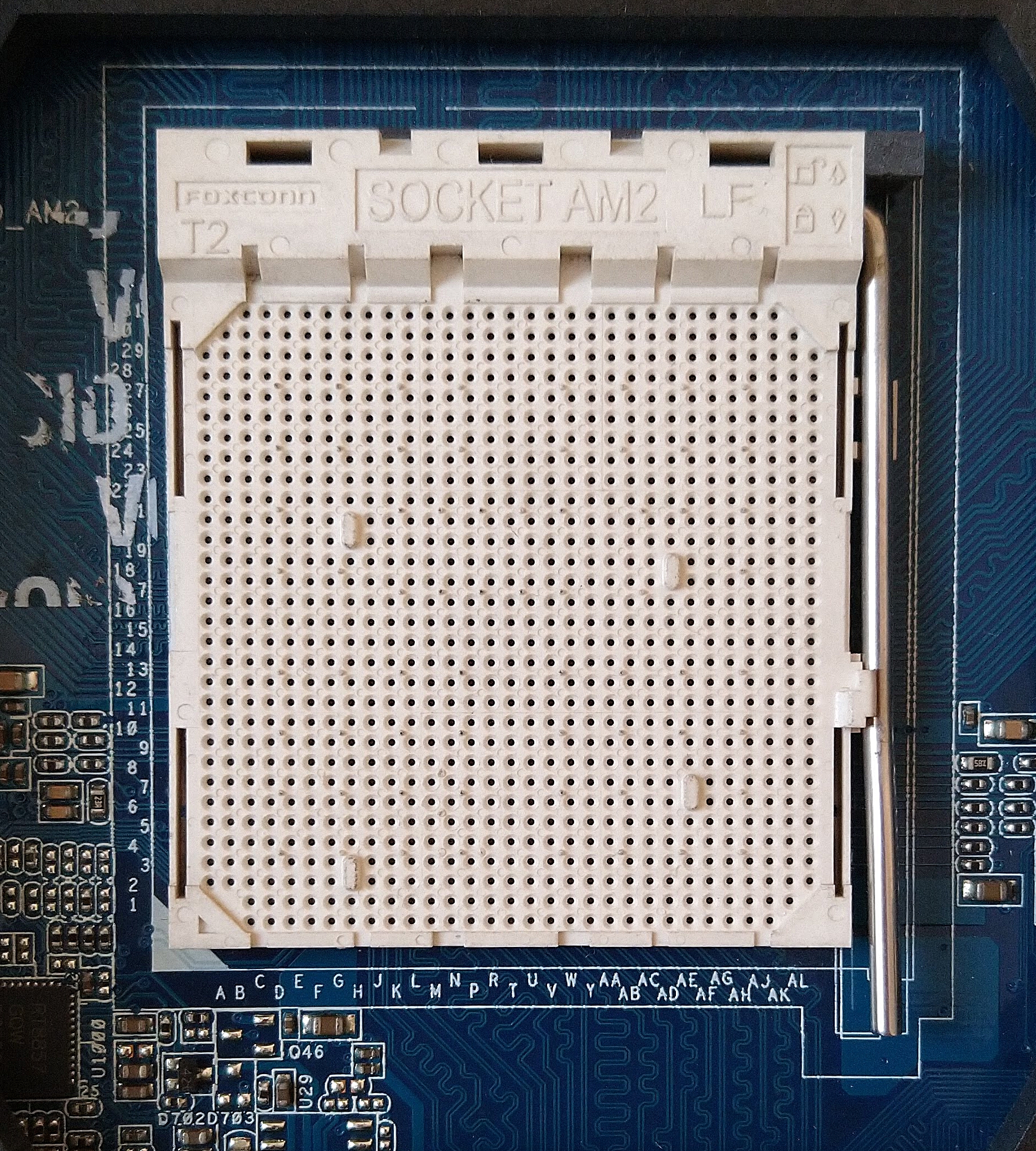
The CPU socket is a slot dedicated to housing the CPU for your system. Depending on the type of motherboard, you can have one or two slots, to store up to two CPUs. A motherboard with two CPUs is very intense. This kind of motherboard would probably be designated for servers. It’s very much overkill for everyday use and even gaming. As mentioned before, the CPUs that would properly fit in these sockets are dictated by the motherboard and it’s chipset.
It’s extremely important that when placing your compatible CPU in the socket, you do it delicately and correct. The pins on the CPU can be damaged on the CPU socket if placed incorrectly. This could ruin your CPU irreversibly. If you somehow put it in wrong, latch it down to the CPU and start it, it could also damage your motherboard, rendering it useless.
Note: Systems normally won’t run if a CPU is not detected on the motherboard. That includes improperly installed ones as well.
If you did unfortunately manage to bend the pins, you could try to painstakingly correct the pins into a straight line in it’s original shape. It’s not advised and takes a lot of effort, precision, gentleness (and seemingly luck) to try to fix. CPUs are not cheap, nor are some motherboards, so it’s best to take your time with installing the CPU into the socket.
Manufacturers recognize the difficulty in identifying the right orientation for the CPU. On one edge of the top of the CPU, there is a golden triangle. That edge should match up with a triangle imprint on the CPU socket. Even though you identify the direction, you must still be cautious with laying the CPU pins inside the socket safely. As always, please refer to your manuals for installing for further details.
17.ATX Power Supply (24-pin)/ 19.EATX(8-pin)
These pin connectors are the points on the motherboard where the power supply unit (PSU), and provides power to the system. Every desktop/server build you’ll do will require a PSU and you will always connect the 24-pin cable to the motherboard. You will normally use the 8-pin connector port as well. The thing is, you may not use all 8-pins of the 8-pin power supply connector. It is all based on your specific system. The last 3 systems I’ve built had always used the full 24-pin connector as well as 6 pins of the 8-pin connector. Again, please refer to your manual about specific connections.
![Renkforce Current Cable [1x ATX power plug 14-pin - 1x ATX power socket 24-pin.] 25.00 cm Multi-coloured | Conrad.com](https://lowkeyop.com/wp-content/uploads/2020/11/image-3.jpeg)
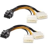
If insufficient power is provided to the system, it won’t start, or attempt to start, but fail. It’s best to calculate what your total power consumption is and make sure to have a PSU that will be able to convert and provide the necessary power for your machine.
18. RAM Slots
RAM stands for Random Access Memory. It is a type of volatile memory for a computer that acts as quick reference to instructions needed for processing code. RAM slots hold these RAM sticks for system. When placing RAM in the slots, it’s important to reference your motherboard manual for which slots to use and direction of slots. Though, RAM sticks may look like they can be placed in either way, it’s not the case. If you look closely, one side of the gap has more pins than the other. Forcing it the wrong way could damage the RAM, causing you to spend more money than anticipated.
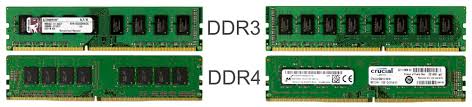
When handling any component of a computer, be sure to be grounded. This means removing any static electricity potentially stored on your hand(s) or body. You can accidentally short them, rendering them useless. This is even more relevant with RAM sticks.
Conclusion
This wraps up this detailed breakdown of a motherboard. Hopefully this helps shed light on what are some common parts , do’s and don’ts when connecting components to them and when to get what to expect when building a system yourself.
Key takeaways you hopefully get from this:
- Knowing the purpose of each component
- Things to be aware of when choosing parts to connect to your mobo
- Your Motherboard won’t work without a correct CPU and PSU to power the system.
- Refer to the manual that comes with your motherboard.
Feel free to comment below.
Cordell Kennerly

Cordell Kennerly has worked in various capacities of Software Development and Engineering for over 10 years. In parallel with gaining experience in software development, he has experience with RDBMS and No-SQL databases, and software deployment, PC building and Security
0 thoughts on “A Dissection Of A Motherboard”